|
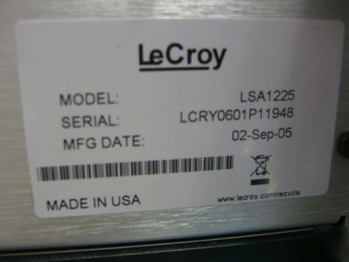
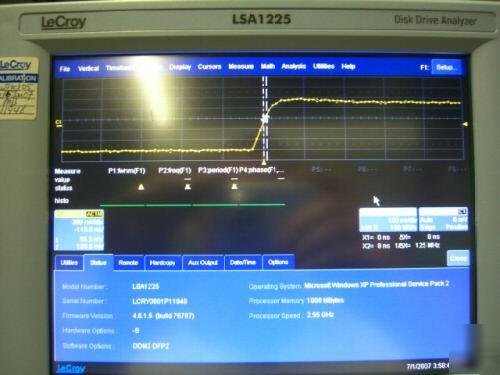
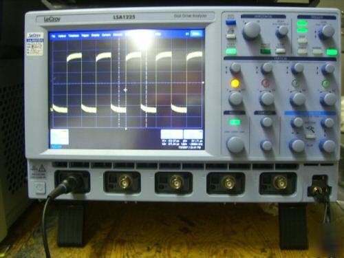
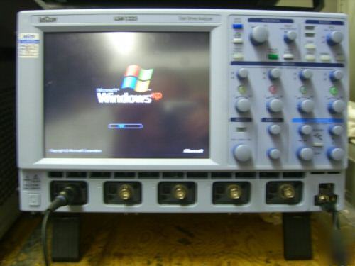
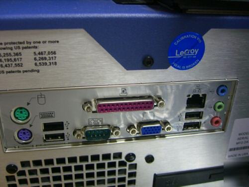
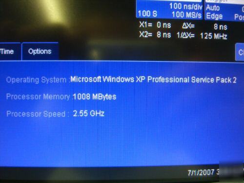
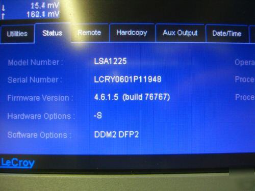
includes intel P4 2.53GHz motherboard with 1 GIG ram running WIN XP, lecroy warranty expires january 2009!!!, manufactured in sept. 2005!! Input Capacitance, using PP007 probe: < 9.5 pF (typical) Input Capacitance of Channel (1/1, 1/10, 1/100): < 20 pF (typical) Input Impedance: 1 Mohms // < 20 pF (10 // 9.5 pF using PP007 probe) Input Coupling: 50 ohms: DC; 1 Mohms: AC, DC, GND Installation (Overvoltage) Category: CAT I Channel to Channel Isolation: > 40 dB @ < 100 MHz (> 30 dB @ full bandwidth) Vertical Resolution: 8 bits; up to 11 bits with enhanced resolution (ERES) Sensitivity: 50 ohms: 2 mV to 1 V/div fully variable; 1 Mohms: 2 mV to 10 V/div fully variable DC Gain Accuracy: ±1.0% of full scale (typical) Offset Accuracy: ±(1.5% of full scale value + 0.5% of offset value + 1 mV) Timebases: Internal timebase common to all input channels; an external clock can be applied at the auxiliary input Time/div Range: 20 ps/div to 1000 s/div (10 s/div in Auto trigger mode) Math & Zoom Traces: 4 math/zoom traces standard Clock Accuracy: Jitter Noise Floor: 2 ps rms typical (5 ps warranted) @ 100 mV/div Time Interval Accuracy: Clock Accuracy + Jitter Noise Floor Sample Rate & Delay Time Accuracy: equal to Clock Accuracy Trigger & Interpolator Jitter: Channel-to-Channel Deskew Range: ±9 X time/div setting; 100 ms max. each channel Interpolator Resolution: 1.2 ps External Timebase Clock: 100 MHz, 50 ohms impedance External Sample Clock: (2-channel operation only): DC to 1 GHz; 50 ohm or 1 Mohm, BNC input Roll Mode: Switches automatically at > 0.5 s/div or sampling rate < 20 kS/s Single-shot Sample Rate/Ch: 5 GS/s Random Interleaved Sampling (RIS): 200 GS/s Trigger Rate: 125,000 waveforms per second Single-shot: For transient and repetitive signals: 20 ps/div to 10 s/div Sequence Time Stamp Resolution: 1 ns Time Resolution (minimum, single-shot): 200 ps (5 GS/s); 100 ps (10 GS/s) Averaging: Summed averaging to 1 million sweeps; Continuous averaging to 1 million sweeps Enhanced Resolution (ERES): from 8.5 to 11 bits vertical resolution Envelope (Extrema): Envelope, floor, roof for up to 1 million sweeps Interpolation: Linear, (sinx)/x Modes: Normal, Auto, Single, and Stop Sources: Any input channel, External, Ext/10, or line; slope and level are unique to each source (except line) Pre-trigger Delay: 0 to 100% of memory size (adjustable in 1% increments or 100 ns) Post-trigger Delay: The smaller of 0 to 10,000 divisions, or 86,400 seconds Holdoff by Time or Events: Up to 20 s or from 1 to 99,999,999 events Internal Trigger Range: ±4.1 div from center (typical) Maximum Trigger Frequency: 2 divisions at > 750 MHz with Edge Trigger; 1 division at 750 MHz 750 MHz max. with SMART Trigger @ >/= 10 mV (subject to bandwidth limit of scope) Trigger Level DC Accuracy: ±3% of full scale ±2 mV (typical) External Trigger Range: EXT/10 ±4 V; EXT ±400 mV Edge/Slope/Line: Triggers when the signal meets the slope and level condition. State or Edge qualified: Triggers on any input source only if a defined state or edge occurred on another input source. Delay between sources is selectable by time or events. Dropout: Triggers if the input signal drops out for longer than a selectable time-out between 2 ns and 20 s. Pattern: Logic combination (AND, NAND, OR, NOR) of 5 inputs (4 channels and external trigger input). Each source can be high, low, or don't care. The High and Low level can be selected independently. Triggers at start or end of pattern. SMART Triggers with Exclusion Technology Glitch: Triggers on positive or negative glitches with widths selectable from 600 ps to 20 s or on intermittent faults. Signal or Pattern Width: Triggers on positive or negative pulse widths selectable from 600 ps to 20 s or on intermittent faults. Signal or Pattern Interval: Triggers on intervals selectable from 2 ns to 20 s. Timeout (State/Edge Qualified): Triggers on any source if a given state (or transition edge) has occurred on another source Delay between sources is 10 ns to 20 s, or 1 to 99,999,999 events Exclusion Triggering: Trigger on intermittent faults by specifying the normal width or period. Autosetup: Automatically sets timebase, trigger, and sensitivity to display a wide range of repetitive signals. Vertical Find Scale: Automatically sets the vertical sensitivity and offset for the selected channels to display a waveform with maximum dynamic range. Probes: 4 X PP005 probes; optional passive and active probes are available Probe System – ProBus: Automatically detects and supports a wide variety of compatible probes Scale Factors: Automatically or manually selected depending on probe used Type: Color 8.4-inch flat panel TFT LCD with high resolution touch screen Resolution: SVGA; 800 x 600 pixels Real Time Clock: Date, hours, minutes, and seconds displayed with waveform; accurate to ±50 ppm; SNTP support to synchronize to precision internet clocks Number of Traces: Maximum of eight traces; simultaneously displays channel, zoom, memory, and math traces Grid Styles: Single, Dual, Quad, Octal, XY, Single+XY, Dual+XY Waveform Display Styles: Sample dots joined or dots only Analog and Color-graded Persistence: Variable saturation levels; stores each trace's persistence data in memory Persistence Selections: Select analog, color, or 3-D Trace Selection: Activate Analog Persistence on all or any combination of traces Persistence Aging Time: From 500 ms to infinity Sweeps Displayed: All accumulated or all accumulated with last trace highlighted Display up to 4 Math/Zoom traces Processor: Intel 2.53 GHz P4 or better with MS Windows XP platform or win2000 Waveform: M1, M2, M3, M4 (Store full-length waveforms with 16 bits/data point.) Or save to any number of files (limited only by data storage media). Front Panel and Instrument Status: Save to the internal hard drive or to a USB-connected peripheral device. Remote Control: Through Windows Automation or LeCroy remote command set GPIB Port (optional): Supports IEEE-488.2 Ethernet Port: 10/100Base-T Ethernet interface (RJ-45 connector) USB Ports: 5 USB ports (one at front of scope) support Windows compatible devices. External Monitor Port (standard): 15-pin D-Type SVGA compatible DB-15; connect a second monitor to use dual monitor display mode Serial Port: DB-9 COM1 port (not for remote control of scope) Signal Types: Select External Trigger or Clock input on front panel. Signal Types: Select from calibrator or control signals output on front panel. Calibrator Signal: 250 Hz to 1 MHz square wave or DC level; 5 mV to 1.0 V (selectable) into 1 kohms Control Signals: trigger enabled, trigger out, pass/fail status, square, DC level Display up to eight math function traces (F1 to F8). The easy-to-use graphical interface simplifies setup of up to two operations on each function trace. Function traces can be chained together to perform math-on-math. enhanced resolution (to 11 bits vertical) trend (datalog) of 1,000 events Display any 8 parameters together with statistics, including their average, high, low, and standard deviations. Histicons provide a fast, dynamic view of parameters and wave shape characteristics. fall time (90-10%, 80-20%, @ level) rise time (10-90%, 20-80%, @ level) Test multiple parameters against selectable parameter limits at the same time. Pass or fail conditions can initiate actions including: document to local or networked files, email the image of the failure, save waveforms, send a pulse out at the front panel auxiliary BNC output, or (with GPIB option) send a GPIB SRQ. Jitter and timing analysis (JTA2) This package provides jitter timing and analysis using JitterTrack (time), Histogram (statistical) and JitterFFT (frequency) views for common timing parameters, and other useful tools. Jitter and Timing parameters with JitterTrack graphs of: Duty Cycle Error (Delta Width) edge@lv parameter (counts edges) Histograms expanded with 19 histogram parameters and up to 2 billion events Trend (datalog) of up to one million events Persistence Histogram; Persistence Trace Disk Drive Measurement Package (DDM2) - Standard This package provides disk drive parameter measurements and related mathematical functions for performing disk drive WaveShape Analysis. Trend (datalog) of up to one million events Histograms expanded with 19 histogram parameters and up to 2 billion events Digital Filter Package (DFP2) - Standard * The pass-band gain of all filters (except custom) is normalized to 1. * FIR Coefficients: 2000 max. * Filter Kinds: high pass, low pass, band pass, band stop, raised cosine, raised-root cosine, Gaussian, custom * IIR Filter Types: Butterworth, Chebyshev, Inverse Chebyshev, Bessel Auto Calibration: Ensures specified DC and timing accuracy is maintained for 1 year minimum. Power Requirements: Single phase, 100 to 240 Vrms (±10%) at 50/60 Hz (±5%); or single phase, 100 to 120 Vrms (±10%) at 400 Hz (±5%); Automatic AC voltage selection Power Consumption: On State: 400 watts (400 VA) max. depending on accessories installed (internal printer, probes, PC port plug-ins, etc.). Standby State: 12 watts Physical Dimensions (HWD): 211 mm x 355 mm x 363 mm (8.3 in. x 13.9 in. x 14.3 in.); height measurement excludes foot pads calibration recommended yearly Optional service programs include extended warranty, upgrades, and calibration services. Storage (non-operating): –20 to +60 °C Operating: 5 to 80% RH (non-condensing) up to 30 °C; upper limit derates linearly to 50% RH (non-condensing) at 40 °C Storage (non-operating): 5 to 95% RH (non-condensing) as tested per MIL-PRF-28800F Operating: 3048 m (10,000 ft) max. at ≤ 25 °C Storage (non-operating): 12,192 m (40,000 ft) Operating: 5 Hz to 500 Hz, overall level: 0.31 grms, 15 minutes in each of 3 orthogonal axes Non-operating: 5 Hz to 500 Hz, overall level: 2.4 grms, 15 minutes in each of 3 orthogonal axes Functional Shock: 20 g peak, half sine, 11 ms pulse, 3 shocks (positive and negative) in each of 3 orthogonal axes, 18 shocks total Conforms to EN 61326-1, EN 61010-1 The oscilloscope meets requirements of EMC Directive 89/336/EEC for Electromagnetic Compatibility and Low Voltage Directive 73/23/EEC for Product Safety. EMC requirements for electrical equipment for measurement, control, and laboratory use. EN 55011:1998 +A1:1999, Radiated and conducted emissions (Class A)* EN 61000-3-2:2001 Harmonic Current Emissions (Class A) EN 61000-3-3:1995 +A1:2001 Voltage Fluctuations and Flickers (Pst = 1) * To conform to Radiated Emissions standard, use properly shielded cables on all I/O terminals. This is a Class A product. In a domestic environment this product may cause radio interference, in which case the user may be required to take appropriate measures. EN 61000-4-2:1995 +A2:2001* Electrostatic Discharge (4 kV contact, 8 kV air, 4 kV vertical/horizontal coupling planes) EN 61000-4-3:2002* RF Radiated Electromagnetic Field EN 61000-4-4:1995 +A2:2001* Electrical Fast Transient/Burst (1 kV AC Mains, 0.5 kV I/O signal/control) EN 61000-4-5:1995 +A1:2001* Surges (1 kV AC Mains, 0.5 kV I/O signal/control) EN 61000-4-6:1996 +A1:2001* RF Conducted Electromagnetic Field (1 kV / 0.5 kV common mode / differential mode - AC Mains) EN 61000-4-11:1994 +A1:2001* Mains Dips and Interruptions (1 cycle voltage dip, 100% short interruption) * Meets Performance Criteria "B" limits during the disturbance, product undergoes a temporary degradation or loss of function of performance which is self recoverable. Safety requirements for electrical equipment for measurement, control, and laboratory use. The oscilloscope has been qualified to the following EN 61010-1 limits: Installation Categories II (Mains Supply Connector) & I (Measuring Terminals) Pollution Degree 2 (Normally only dry non-conductive pollution occurs. Occasionally a temporary conductivity caused by condensation must be expected.) Protection Class I (Provided with terminal for protective ground) Canadian Standard: CSA-C22.2 No. 1010.1-92 (We do not proofread any ads submitted by members) |
Brandy_Herrera@desmoines-classifieds.com (Brandy Herrera) for more information. Your emails will be instantly forwarded to the poster's private address.