|
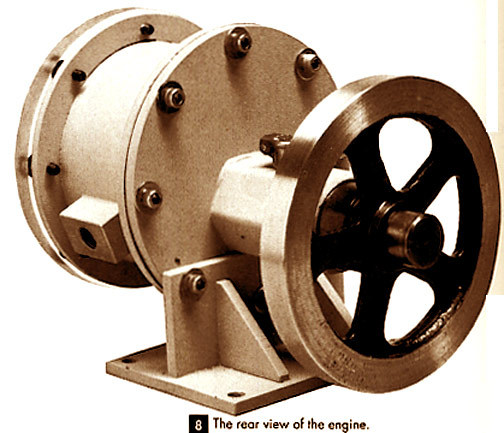
bounce, yer money order will get lost in the mail and yer dog won't come home. click on our "Contact Us" icon above for the quickest response to your questions. HOW TO MAKE AN ELLIPTICAL ROTARY ENGINE HOW TO MAKE AN ELLIPTICAL ROTARY ENGINE HOW TO MAKE AN ELLIPTICAL ROTARY ENGINE HOW TO MAKE AN ELLIPTICAL ROTARY ENGINE HOW TO MAKE AN ELLIPTICAL ROTARY ENGINE HOW TO MAKE AN ELLIPTICAL ROTARY ENGINE HOW TO MAKE AN ELLIPTICAL ROTARY ENGINE HOW TO MAKE AN ELLIPTICAL ROTARY ENGINE HOW TO MAKE AN ELLIPTICAL ROTARY ENGINE If you're a model engineer or a machinist then the magazine Projects In Metal is familiar to you. If not it should be. Projects In Metal is a spinoff of The Home Shop Machinist, the authority on machining and the like. This Featured Project from "Metalworking Two" is just one of the 64 articles you'll find here from the magazine "Projects in Metal". Published in 1990 and 1991, these were the years "Projects in Metal" started maturing into a wellspring of information on the machining topic. Without a lack of articles on machining, "Projects in Metal" was launched in January 1988 and was met with immediate success. Robert Scott Burns, in his 1854 book "The Steam Engine" describes a rotary engine with an elliptical bore. This engine had a rotor of fixed length that rotated on an offset power shaft and contacted the elliptical bore in all positions. This original engine had a cylinder 24" long with an elliptical bore of 20.12" by 18.62". It was said to have an output of 30 horsepower at 32psi of steam. The model described here is based on the original but is not identical in details. An elliptical boring fixture for the lathe is not required to make this model. No claim to originality is made for the design of the mechanism as it is based on one made many years ago for turning oval picture frames. You're going to find entirely new articles published nowhere else but Projects in Metal. You haven't seen the projects, but you probably know the names. Harold Mason, Philip Duclos, Robert Hedin, Guy Lautard, Bill Davidson, Bob Washburn, Ed Dubosky, Dick Torgerson, Steve Acker, and Deene Johnson just to name a few. Here each author introduces their helpful and fun projects. Tooling projects often involve a Morse taper shank or a special shank for something like a chuck body. Writers frequently just tell us to machine the taper in the usual way. Several people have asked me, "What is the usual way?" But we can't expect "Projects in Metal's" editor to burden every tooling article with complete taper turning instructions; doing so would be a repetitious waste of space. Let's discuss the options here one time and look at a simple method for turning tapers and angled shoulders. There are three common taper turning methods: the taper attachment, tailstock setover, and accurately setting the compound. Join me as I give you the information on all three! Make a 5-C Collet Closer for your Lathe My old Atlas/Craftsman 12" lathe served me well for many years, but each time I had to saw off a piece of stock larger than 3/4" diameter, and each time I had a problem trying to hold small pieces accurately, I would stop and think of how nice it would be to have a machine that would pass larger stock through the spindle so I could use a set of 5C collets for precision work. Well, the opportunity finally presented itself. The old machine was sold and a new machine of Taiwanese extraction was purchased - the important part for the purposes of this article being that it has a No. 5 Morse taper in the headstock spindle. The purchase of the new machine solved the problem of the too-small spindle bore, but alas, the budget did not contain another $250 for a collet closer. At this point, I began to think of a do-it-yourself solution. A search of suppliers' catalogs presented an item that seemed a likely starting point - a No. 5-to-No. 3 Morse drill reducing sleeve. These sleeves come in two varieties - hard all over, or with only the tang hardened. The latter is what I used. The advantage of starting here is that the hard part (the No. 5 external taper) is already done with a nice ground finish. All that is needed now is to make the inside fit a 5C collet. The sleeve will fit most of the way into the spindle, so the collet must be kept flush with the end of the adapter. Make a Power Feed Ball Turning Fixture Making a power feed ball turning fixture was a fun project. It took but a few hours, and makes balls so smooth they don't even need to be polished. The final cut chip comes off in one piece. The fixture can be put on the lathe in very few minutes, anytime you are in need of making metal balls for ball handles or the like. The fixture was made for my 9" South Bend lathe. However, by altering the dimensions, one could be adapted for other lathes. I made this fixture primarily because I needed to fabricate many ball handles for the "quorn" type workholding fixture I made for my bench grinder. Since completion of the turning fixture, I've found that the ball handles produced by it are very handy to use on other machines and fixtures, in place of using wrenches. What makes this boring head different is that is does not have a dovetail slide. The movable block slides on round rails. It is not a heavy duty unit, but works well with small bars. The body of the prototype is made of aluminum but would be more durable in steel. The lower block slides on two round rails screwed and keyed to the upper block. A 40 tpi screw with a calibrated dial moves the lower block. Setscrews with brass plugs are used to lock the movement. Two boring bar holes in the lower block allow a range of hole sizes to be bored. How to Make A Coaxial Indicator The principle of this indicator is not the accuracy of the gage in thousandths of an inch, but rather needle deflection. Just as with a wiggler gage setup, we are looking for minimum or no needle movement. The plans called for a large dial gage, having its plunger coming out the top, I didn't have such a gage, so I used a modification that I'll show you in the article. All I needed to get started was a milled groove and a peg to hold the gage. Make a High Efficiency Screw Press Most home shops need a small press for installation of bushings and ball bearings, work on tapered mandrels, and for other force-fit requirements. Three types of presses are found in the home shop. When assembly loads are high, with large work and rough fits, the hydraulic press has no equal. However, unless you use the hydraulic press frequently and develop a light "calibrated" touch, it's very easy to apply excessive pressure to smaller work that "won't move," resulting in collapsing a bushing, cracking a casting, or otherwise spoiling the day. The arbor press is a quick-acting tool ideal for installing dozens or hundreds of identical bushings in bored, or workpieces on mandrels, in a limited production situation. Even the smallest models are expensive to purchase; and the rack-and-pinion design makes this type a bit difficult, although not impossible, to build in the home shop. We're going to talk about the third and simplest type, a small bench mounted screw press; very easy and economical to build. This press is smooth running and makes it easy to feel the load applied to smaller parts. The term "high-efficiency" refers to reducing friction losses through incorporation of a thrust bearing in the pressure foot and selecting an Acme thread for the pressure screw. Surprising pressure can be developed by hand turning the 8" handwheel. Make a Small Sheet Metal Brake I've often needed small sheet metal boxes, shelves and various lightweight parts. My floor plan has very little space left for new equipment, but my need for large capacity is also limited, so I designed and built a brake to fit my needs. My sheet metal brake accepts a maximum width of 17-1/2" and weighs only 53 pounds. A brake twice that width would weigh about 400 pounds, according to cube law. With this tool, I've made custom fitted containers for milling cutters, collets, a tapping attachment, and other accessories, adding hinges and latches obtained at the hardware store. By using a pop rivet tool to join the sheet metal parts, I made a very lightweight and sturdy TV stand. The three basic members of the brake are: the base, on which the sheet metal is placed for bending; the clamp, which holds it in place on the base; and the bending plate. A small handle and eccentric shaft on each side of the brake near the back transmits back-and-forth motion for positioning the clamping fingers to the desired distance from the edge of the bending plate. This adjustment allows some control on the sharpness of the bend and makes allowance for the thickness of material used. Make a Single Wheel Knurling Tool Some time ago I was poking through an old issue of popular science, smugly enjoying the many advances that have been made in four decades since it was printed. Then I was brought back to earth rather quickly. Staring back at me from the old magazine was a reminder that many of us do thing much the same way they have been done since some processes originally were developed in metalworking. Fortunately, it can be pure enjoyment running old fashioned engine lathes, and dialing coordinates in by hand on milling machines. But what stopped me was a gadget that jarred my memory to focus on the four small steel disks sitting in a box of miscellaneous pieces of broken or worn-out tooling. They represent one of the most versatile surface finishing tools available for a lathe: a knurling tool. Knurling is a widely used process for improving the function of a piece by making it easier to grip. And it is often used to improve the cosmetic appearance of an otherwise rather plain looking part. There is another less obvious advantage to knurling. Most lathe operations involve some type of cutting or other method of metal removal. But knurling is a displacement process. Instead of removing metal, it is rearranged. As a result, a knurled surface is raised to a slightly larger diameter. This can be extremely handy for a piece that needs to be a press fit but acts more like a slip fit. Knurling is one of the very few situations where it is possible to increase the diameter of a workpiece by machining it. Plus 33 more projects involving techniques and making lathe accessories. The mathematics of a dividing head Single thread worm drives in the home machine shop Simple tooling for model size shoulder bolts Risers for a 6" Atlas or Craftsman lathe Spindle driving handle for Emco Super II lathe Improving the quick-change on a small lathe A tailstock tap and die holder Bed extension for Atlas and Craftsman Lathes Stay put lathe carriage lock wrench A lathe rack repair using a single point tool Adjustable pop-stop for the Myford lathe Z-axis downfeed for a mill/drill machine Variations on a button V-Block Indicator clamps for lathe beds Conservative coolant applicator Metal spinning with a lathe is a process that gradually transforms a revolving disc of sheet metal into a variety of shapes - perhaps a vase, a bowl, or a lamp base. It is regrettable that many of us who have the facilities to practice this ancient craft have complete ignored it - for there are times when the ability to spin metal would be invaluable to a home shop machinist. This short article on metal spinning is intended for the beginner. Only the barest minimum of tool and fixtures will be described, thus making it easier for the uninitiated to get started on a simple project. Build a Two-Cylinder Oscillating Steam Engine Two oscillating engines geared to the same flywheel make up this design. I chose the arrangement because a simple manifold connects the cylinders, and with the cranks 90 degrees apart, the engine is self-starting. The manifold has a control valve for forward and reverse. It will also stop the engine and vary the speed. A uniflow system is used with the exhaust passage at the center of the cylinder. The steam intake is at the top of the manifold and the exhaust on either side of the frame. The frame and cylinders are made of brass with soft-shoulder construction; silver solder could also be used. Make an Adjustable Angle Plate Working each day in a first class machine shop with al the best machines and tooling makes me want more attachments and tools for my home workshop. I was using an adjustable angle plate one day and decided it would be very useful to have at home. Make a Quick and Easy Electric Foundry/ I built Dave Gingery's charcoal furnace in a 5-gallon metal bucket as he described in his book about charcoal foundries. I found that the sand clay mix had a tendency to crumble, so I redid it using castable refractory. I still use it and a larger unit made from a 55-gallon drum. As cold and rainy weather came on, I needed to make some small castings inside the shop without burning the shop down. About that time, my mother-in-law had me replace an eye on her electric cookstove because the small disk in the center of the element had rusted out. I hit on the idea of putting the electric element inside the 5-gallon refractory lined bucket, and propping it up on ceramic insulators to level it. I attached high temperature wire to the terminals with No. 6 screws, wrapped the terminals with fiberglass cloth, and brought the wires out through the pipe I used for forced air when using the unit for a charcoal furnace. I connected the wires to a stove pigtail and plugged it in. A lightweight cover without an air hole was made from an old plan. Make A Tool and Cutter Grinder The rough grinding of lathe tools by hand on a bench grinder with frequent dipping in water coolant is easy enough. But the precise finish on the cutting edge, particularly of threading and form tools, and the resharpening of milling cutters, requires special equipment to hold the tool and guide it in the proper path across the wheel. Commercial tool and cutter grinders are designed for production and universal application, but my need will never go beyond sharpening a few lathe tools and end milling cutters of 1/2" maximum diameter. In this design, therefore, I couldn't draw much from industrial models. It weighs only 50 pounds and occupies barely more than a square foot of bench space. The small 1/20hp motor drives a 4" cup wheel at 3600 rpm. The airflow spindle operates on only 15 psi at less than 0.2 cfm, conserving compressed air. The height of the wheel is fixed and need not be adjusted because the tilt adjustment always keeps its center at the same height. Some call it a skill, some call it a gift, and some call it just sheer luck. I call it a miracle. I'm referring to the thankless task of freehand grinding small tool bits to an efficient and presentable shape. Unquestionably a person who grinds tools day after day will become quite proficient after a while. The average home machinist, however, doesn't sharpen tools very often. Once he has put together a basic set of bits (left-hand and right-hand for steel, brass, and aluminum), he will seldom have to regrind for many months or even years. A light touch with an abrasive stick will keep the tools in shape almost indefinitely unless, of course, they have been abused. In the above paragraph the operative words are: "...a basic set of tool bits..." This sounds simple but, unless additional equipment is available, it could mean soul-searching frustration. Back in 1938, when I was much younger and more innocent than now, I bought myself a British-made Wolf bench grinder and a handful of 1/4" square HSS tool bits, convinced that it would be plain sailing from then on. It did not quite turn out that way. Rough shaping of the bits was not too difficult. The coarse stone cuts cleanly and not much heat is generated. Life became far more complicated when I moved over to the fine-grained wheel. I could hold the bit against the stone for some twenty-odd seconds before having to dip it in water. (Textbooks discourage this practice, since sudden cooling can cause surface cracks. This is true for large forged tools, where the cutting edge can discolor markedly before the shank becomes too hot to hold. Handheld bits cannot get hot enough for this to happen, since even the hardiest of machinists couldn't stand more than some 60°C.) Here my troubles began: In nine times out of ten – perhaps 99 out of 100 would be nearer the truth – after cooling the tool I couldn't bring it back to the original angle again. The net result, although I always ended up with the cutting edge I wanted, was an unattractive n-faced polygon. This did not impair performance, but it injured my pride. Obviously some drastic measures had to be taken. Height gauge conversion and attachments Wire clamps - a unique third hand A glass cutting helper for your drill press Conversion piece two headed bolt with nut A "skypod" for the traveling photographer Any one of these projects is worth the small cost of the book! If you're just learning about machining or you're an old pro this book has the information you need and it belongs in your head. Now's your chance to get ahead - don't miss it! 8-1/2 X 11" Hardcover, 255 pages, profusely illustrated with photographs and working drawings. Visit my MarketplaceAdvisor Gallery! Power Tools for Power Sellers! Phone: (***) 744-4449 M-F 9:00 to 4:00 Pacific Standard Time This item has been seen by alt people! (We do not proofread any ads submitted by members) |
C-Slater@desmoines-classifieds.com (Cheryl Slater) for more information. Your emails will be instantly forwarded to the poster's private address.